In our work we often get asked by customers about the two different types of DAS unit commonly found and which they should use. As it’s our tool of choice for extracting info on the condition of cables, we thought it was time to put together some of our thoughts on the topic.
A standard device for testing the quality of an optical fibre installation in subsea cables is an OTDR (Optical Time-Domain Reflectometer). An incoherent pulse of light is sent along a fibre, and the amplitude of the reflected light, when averaged over a number of pulses, tells us if there are bend losses, splices, connectors etc. The time delay between the launch and receive of the reflected signal tells us where the features are. If a coherent laser is used as the light source something different happens and with no time averaging early Distributed Acoustic Sensing (DAS) is born.
The coherency of the laser causes interference between light that is backscattered from different parts of the fibre, and the amplitude of the reflected light from each location is therefore very sensitive to change in the optical path length of the fibre (i.e. strain change or temperature change). The sensitivity to change is somewhat randomised in both magnitude and direction, and this led to changes in the optical architecture of DAS to enable optical phase to be tracked. An intensity only DAS is often referred to as Qualitative DAS (COTDR) and a phase and amplitude tracking DAS is similarly referred to as Quantitative DAS or Phase Coherent DAS.
Both interrogator types make measurements along the fibre giving independent outputs from sections of fibre a few metres long. These length of these sections of fibre is typically called the gauge length. Shorter gauge lengths give better spatial resolution but lower sensitivity to change.
A great source of information on the physical principles of DAS is provided in the recently updated SEAFOM MSP-02 V2.0 “DAS Parameters Definitions and Tests”.
This blog post is concerned about how measurements from these devices on the same cables provide a difference in output – when should each be used?
Qualitative DAS
These units are cheaper and easier to make but do have a high enough sensitivity. Because of these reasons they still have use in monitoring subsea cables. They are excellent devices for pinpointing specific events such as vessels or the arcing caused by a thumper during fault location. It is important to note that this detection approach comes with some major limitations. Firstly, any practically relevant low frequency information is distorted and lost, secondly there is no information on the sense/sign of the stimulus (tension/compression or heating/cooling), and thirdly a noisy environment at low frequencies will tend to scramble higher frequency signals creating harmonics that are not actually present in the signal. This signal distortion is predominantly caused by being unable to track the optical signal from cable strain larger than around 0.3 microns over each gauge. All significant low frequency signals and larger magnitude high frequency signals cause more strain than this, and result in this loss of information.
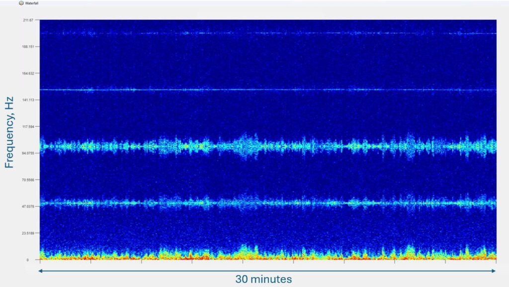
This figure is a spectrogram of 30 minutes of data from a section of a UK export cable, 30 km from the shore. It shows the distortion of a pure 3 phase 50Hz electrical signal in a power cable by the action of waves which are occurring at a much lower frequency. This low frequency signal causes the sensitivity of the DAS to flip between positive and negative and leads to side bands in the frequency observed hence we see distortion in the 50Hz and upper multiples of the 50Hz signal which are not present in the cable. Care is needed on interpretation.
In qualitative systems, the maximum range is strongly correlated to the gauge length. To get distances longer than around 20 km, the length of the light pulse has to be increased to increase the amount of launched light. This reduces the spatial resolution.
Another issue that strongly affects Qualitative systems is an effect called fading. Fading occurs due to the random nature of the backscattered reflections, occasionally these can add together in such a way to give either a null response to a stimulus or no significant backscattered light. In a quiet environment, these fading effects can render specific channels useless for minutes before environmental conditions change enough to restore sensitivity. In a subsea environment this is generally less of an issue due to the noise of the environment, but it is something to be aware of.
Quantitative DAS
In a quantitative system, the optical backscatter is measured in a different way. Instead of just measuring the amplitude of the backscattered light, the optical phase of the light is measured. There are a number of techniques to achieving this, but all are more complex than simply measuring the amplitude. If the phase is measured, then absolute information about the strain or temperature change can be established Since the fibre effectively becomes a double pass interferometer, a gauge length strain of 0.5 optical wavelengths would give us around one ‘fringe’ (2Pi radians). The wavelength of the light used (typically 1550nm in vacuum)is very close to 1 micron in glass. Straining the fibre also modifies the refractive index of the fibre so in practice we end up with around 10 radians of phase change for each micron of strain. A similar calculation can be done for temperature sensitivity, here we typically get around 1000 radians of phase change for each degree change in temperature (depending on the cable construction and the gauge length). Typical sensitivities of phase measurement are around 0.001 radians (when averaged over a second), so the origin of the extreme sensitivity to change becomes clear.
A quantitative system has a similar sensitivity to a qualitative system (when not faded), but since the changes in phase are tracked, temperature and strain changes can be observed and understood. We can now quantify changes in temperature of the cable, or measure the effect of strain on the fatigue life. Another advantage of tracking phase rather than amplitude is that the distortion of signals is vastly reduced, as discussed above. This creates measurement problems and is best avoided. For example, we may be interested in looking for a 300 Hz grounding signal and need to be sure that the 300 Hz signal that is observed is real, not just a measurement artefact.
Quantitative systems have also had the benefit of much development in recent years, pushing the maximum range to further than possible with older qualitative machines (without compromising spatial resolution) and also reducing the problems of fading. However, as discussed, they are more expensive, and less amenable to reduction in size and cost. However, the absolute nature of the output enables a much greater array of use cases and they remain the recommended route for most applications.
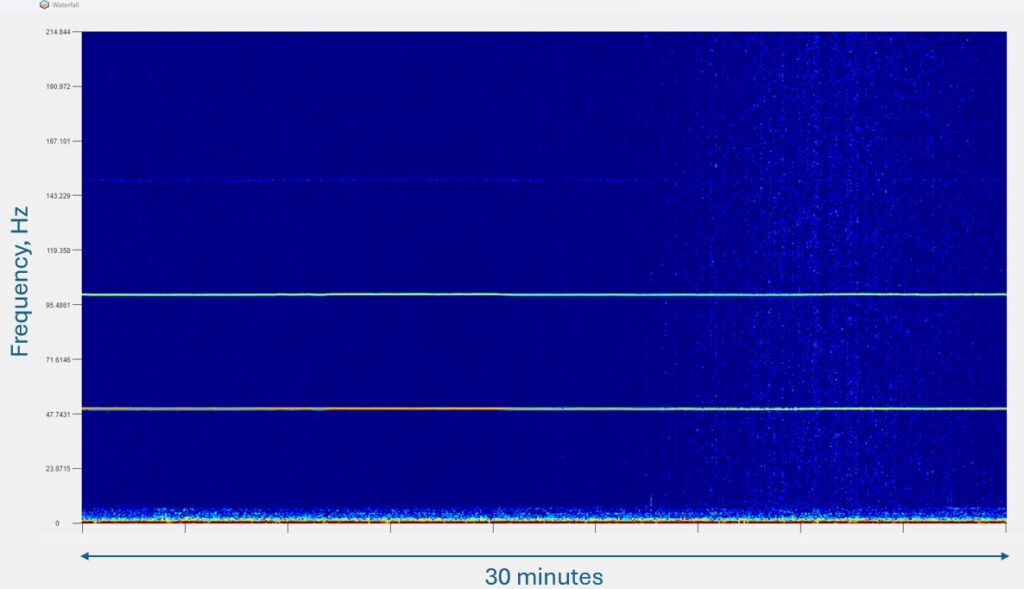
This figure shows a spectrogram from the same section of export cable shown the figure above, but this time taken using a phase coherent DAS. The 150 Hz harmonic is very faint, and in this case real. The low frequency noise from waves is seen at less than 1 Hz, as it should be.
Conclusions
In summary, qualitative units are best used as a cost effective solution for when specific detection of acoustic events is required – e.g. for locating a failure with a thumper or TDR.
For any sort of quantification or measurement of long-term changes, a quantitative device should be installed. We would always recommend the use of a quantitative device to our clients for permament monitoring systems, but we are often asked to look at data from older qualitative units and these can still deliver value but insight must be taken with an understanding of the inaccuracies of the data.